88 Years of Precision Engraving & Marking Excellence Request a Consultation

Gravotech Marking & Engraving Technology

An engineering-driven examination of the three core technology platforms that power Gravotech permanent identification systems: fiber laser, CNC mechanical, and CO2 laser. Each technology addresses distinct material-process combinations with measurable tradeoffs in speed, depth, contrast, and operating cost.

Three Platforms, One Objective: Permanent Identification

Gravotech develops and manufactures laser sources, motion systems, and control software in-house. This vertical integration gives our engineering team direct control over the marking process chain, from beam generation to final verification.
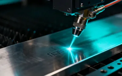
Fiber laser marking process
Wavelength: 1064nm

Fiber Laser Marking

Ytterbium-doped fiber laser sources generate a 1064nm beam ideally absorbed by metals and most engineered plastics. The non-contact process produces permanent marks without material removal in standard annealing mode, or with controlled ablation for deep engraving applications.

Marking Speed Up to 8,000 mm/s
Spot Size 30-80 microns
Power Range 20W / 30W / 50W
Source Life 100,000+ hours
CNC mechanical engraving process
Mechanical

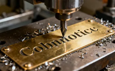
CNC Rotary & Diamond-Drag

Servo-driven X/Y/Z motion platforms paired with high-speed spindles (rotary engraving) or spring-loaded diamond styli (drag engraving). This technology excels at creating tactile, deep marks on metals, laminates, and plastics with physical depth that remains readable even after surface wear.

Depth Control 0.01mm resolution
Work Area Up to 305 x 210mm
Spindle Speed Up to 40,000 RPM
Tool Change Automatic 6-position
CO2 laser engraving and cutting process
Wavelength: 10.6 microns

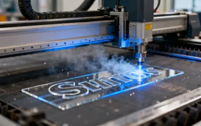
CO2 Laser Engraving & Cutting

Sealed CO2 laser tubes operating at 10.6 micron wavelength interact efficiently with organic and non-metallic materials. Large-format gantry platforms provide work areas up to 1200 x 900mm for signage, industrial marking, and material processing applications requiring both engraving and through-cutting.

Work Area Up to 1200 x 900mm
Power Range 30W to 120W
Resolution Up to 1200 DPI
Materials Wood, acrylic, leather, fabric

Technology Selection Guide

Selecting the correct marking technology depends on four primary variables: substrate material, required mark type, production volume, and regulatory standard. This matrix summarizes the tradeoffs our application engineers evaluate during system specification.

Parameter Fiber Laser CNC Mechanical CO2 Laser
Primary Materials Stainless steel, aluminum, titanium, brass, plastics Brass, aluminum, acrylic, laminates, wood Acrylic, wood, leather, fabric, glass, ceramics
Mark Type Surface annealing, color change, ablation, deep engraving Physical depth engraving, diamond-drag scribing Surface engraving, through-cutting, raster marking
Typical Character Height 0.1mm to 200mm 1mm to 150mm 0.5mm to 500mm
Production Speed Highest (non-contact, galvo-steered) Moderate (physical tool contact) High for organics, moderate for engraving depth
Consumables None (diode-pumped solid state) Cutting tools, diamond styli Laser tube replacement (sealed CO2)
Regulatory Fit UDI, MIL-STD-130, AIAG B-17 MIL-STD-130, industrial nameplates General marking, signage standards

This table represents general guidance. Material-specific results depend on alloy composition, surface treatment, and marking parameters. Contact our application engineers for a process evaluation using your actual substrates.

Marking Process Fundamentals

Understanding the physics behind each marking process enables informed technology selection and parameter optimization.

Laser-Material Interaction

When a focused laser beam strikes a material surface, energy transfer occurs through three mechanisms: absorption, reflection, and transmission. The ratio between these mechanisms depends on the laser wavelength and material properties.

Fiber lasers at 1064nm are efficiently absorbed by metals because this wavelength interacts with free electrons in the metallic crystal lattice. At controlled power densities below the ablation threshold (typically 10^6 W/cm2 for stainless steel), the beam creates a thermally-induced oxide layer that appears as a high-contrast color change without removing material. This "annealing" mark preserves the surface integrity essential for medical instruments and aerospace components that must maintain fatigue life.

Above the ablation threshold, material vaporizes in a controlled manner, creating physical depth marks from 10 to 200+ microns. Our application engineers balance speed, depth, and surface quality by adjusting pulse frequency (20-200 kHz), pulse duration, and hatching parameters for each specific material.

Mechanical Engraving Dynamics

CNC engraving removes material through controlled chip formation. A rotating carbide or diamond-tipped tool follows programmed tool paths while servo motors maintain depth regulation to 0.01mm. The result is a tactile mark with physical depth that remains readable even when surfaces are painted, worn, or contaminated.

Diamond-drag scribing uses a different mechanism: a spring-loaded diamond stylus displaces material laterally without chip formation, creating a fine burnished line. This process is ideal for metal surfaces requiring non-destructive marking, such as calibration instruments and precision measurement tools.

The key advantage of mechanical engraving over laser marking is depth. While laser marks typically penetrate 10-200 microns, mechanical engraving can produce depths exceeding 500 microns — critical for applications where marks must survive aggressive surface treatments, sandblasting, or heavy industrial wear. The tradeoff is speed: mechanical processes are inherently slower due to physical tool-material contact.

Gravotech marking software interface
Unified Software Platform

Gravostyle and Marking Software

Gravotech marking systems operate through Gravostyle, our proprietary marking and engraving software developed in parallel with our hardware platforms. This vertical integration eliminates the compatibility gaps common when using third-party marking software with OEM laser or CNC hardware.

  • DataMatrix & QR Code Generation Built-in 2D code generators with GS1, ISO/IEC 16022, and ISO/IEC 18004 compliance. Integrated verification scoring before marking.
  • Database Connectivity Direct integration with SQL databases, CSV files, and MES/ERP systems for automated serial number sequencing and batch data import.
  • Parameter Libraries Pre-validated marking parameters for 200+ material-process combinations, developed through systematic testing in our materials laboratory.
  • Process Monitoring Real-time power monitoring and marking verification with pass/fail output signals for automated production line integration.

Technology Limitations & Considerations

Every marking technology involves tradeoffs. Understanding these limitations upfront leads to better system selection and realistic production expectations.

Fiber Laser Limitations

  • Cannot efficiently mark transparent materials (glass, clear polymers) without additives or coatings
  • Color marking on metals is limited to specific alloys — stainless steel produces a color spectrum, but aluminum typically yields only grayscale marks
  • Highly reflective metals (polished copper, gold) require higher power settings and may produce inconsistent mark contrast at lower wattages
  • Marking field size is inversely related to resolution: larger fields mean larger spot sizes

CNC Engraving Limitations

  • Physical tool contact means cycle times are 5-20x slower than laser marking for equivalent content
  • Tool wear requires periodic replacement (typically every 5,000-20,000 characters depending on material hardness)
  • Minimum character height is typically 1mm, making micro-marking impractical compared to laser systems
  • Noise and chip generation require extraction systems and may restrict placement in cleanroom environments

CO2 Laser Limitations

  • Cannot mark bare metals — the 10.6 micron wavelength is reflected by metallic surfaces (anodized metals are an exception)
  • CO2 laser tubes degrade over time and require replacement, unlike maintenance-free fiber laser sources
  • Organic material processing generates fumes that require adequate extraction and filtration
  • Cutting depth is limited by power and material — acrylic up to 20mm, wood up to 15mm at practical production speeds

Need Help Selecting the Right Technology?

Send us your material samples and marking requirements. Our application laboratory will conduct a complimentary process evaluation and return marked samples with recommended parameters and cycle time estimates.

Request a Technology Assessment